

.:madworm:.'s photos
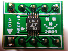
LT1618 on DIP adapter

Logic vs. transistor driver
| |
|
0.1ms/div
2V/div
CH1: Row 1 74HC595
CH2: Row 4 74HC595
This is the good looking control signal for the led matrix row source driver. No overlapping or anything nasty.
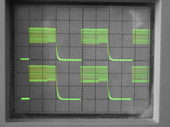
Logic vs. transistor driver
| |
|
5ms/div
2V/div
CH1: Row 1 UDN2981A
CH2: Row 8 UDN2981A
During the LOW period of the signal the cpu has time to service other interrupts and run user code.

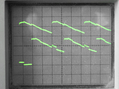
Logic vs. transistor driver
| |
|
2ms/div
2V/div
CH1: Row 1 UDN2981A
CH2: Row 8 UDN2981A
PWM cycle of the rgb led matrix. The interrupt code runs when the signal wiggles. Each little dip scans the whole matrix for one brightness step. 32 scans make up the whole PWM cycle.
You can also observe an interesting effect here. The color that was displayed on the matrix has a hue value of 200, which translates to (0.000,0.666,1.000) in RGB. To set the status bit for a color to "on", the code nees to run 1 command, to leave it "off" nothing has to be processed. Therefore the code finishes a bit earlier. In the photo you'll see a slight difference near 2/3 of the wiggles. The period changes slightly from about 6 to about 7 wiggles per div. In this case you can guess the duty cycle of 0.66 for one color. It only works, as for red it is always 0 and for blue always 1, so only green changes at some point of time.
Logic vs. transistor driver
| |
|
0.1ms/div
2V/div
CH1: Row 1 UDN2981A
CH2: Row 4 UDN2981A
The output of the led matrix row source driver. The signals overlap which explains the ghost images. This was measured without load btw.
I need a digital scope with deep memory to have a look at this type of signal more closely. Triggering is very hard, as there is always some jitter and the signal is not necessarily periodic.
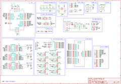
schematic
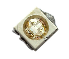
SMD RGB LED - failure mode
| |
|
They don't like the heat and just die. OK might have guessed something like that.
BUT they also suck in flux with all the dirt and just short out! WTF !! Now that I've killed 5 of these, I can only run one of the boards. I need to get more for replacement.
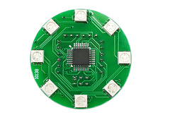
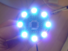
RGB LED Ring - assembled
| |
|
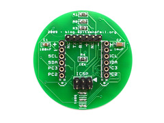
RGB LED Ring - assembled
| |
|
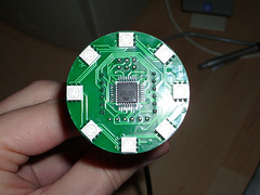
RGB LED Ring - Real PCBs
| |
|
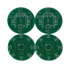
I finally got the PCBs from sparfun. It almost took 6 weeks. 9 days for the letter to get to me. I wonder what takes so much time for "air mail". Must have been my "dear friends" at the customs office again.
Unfortunately this is _not_ the updated design I sent them shortly after I had placed my order, so this PCB version doesn't support auto-reset :-( Let's hope the rest works.
RGB LED Ring - Real PCBs
| |
|
I finally got the PCBs from sparfun. It almost took 6 weeks. 9 days for the letter to get to me. I wonder what takes so much time for "air mail". Must have been my "dear friends" at the customs office again.
Unfortunately this is _not_ the updated design I sent them shortly after I had placed my order, so this PCB version doesn't support auto-reset :-( Let's hope the rest works.
Edit: Works great and will go on my BIKE! 100% illegal taillights ;-)
RGB LED Ring - Real PCBs
| |
|
I finally got the PCBs from sparfun. It almost took 6 weeks. 9 days for the letter to get to me. I wonder what takes so much time for "air mail". Must have been my "dear friends" at the customs office again.
Unfortunately this is _not_ the updated design I sent them shortly after I had placed my order, so this PCB version doesn't support auto-reset :-( Let's hope the rest works.
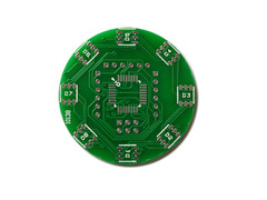
RGB LED Ring - Real PCBs
| |
|
I finally got the PCBs from sparfun. It almost took 6 weeks. 9 days for the letter to get to me. I wonder what takes so much time for "air mail". Must have been my "dear friends" at the customs office again.
Unfortunately this is _not_ the updated design I sent them shortly after I had placed my order, so this PCB version doesn't support auto-reset :-( Let's hope the rest works.
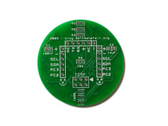
RGB LED Ring - Real PCBs
| |
|
I finally got the PCBs from sparfun. It almost took 6 weeks. 9 days for the letter to get to me. I wonder what takes so much time for "air mail". Must have been my "dear friends" at the customs office again.
Unfortunately this is _not_ the updated design I sent them shortly after I had placed my order, so this PCB version doesn't support auto-reset :-( Let's hope the rest works.
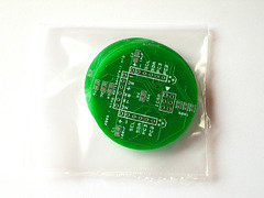
RGB LED Ring - Real PCBs
| |
|
I finally got the PCBs from sparfun. It almost took 6 weeks. 9 days for the letter to get to me. I wonder what takes so much time for "air mail". Must have been my "dear friends" at the customs office again.
Unfortunately this is _not_ the updated design I sent them shortly after I had placed my order, so this PCB version doesn't support auto-reset :-( Let's hope the rest works.
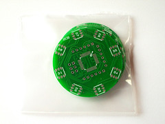
RGB LED Ring - Real PCBs
| |
|
I finally got the PCBs from sparfun. It almost took 6 weeks. 9 days for the letter to get to me. I wonder what takes so much time for "air mail". Must have been my "dear friends" at the customs office again.
Unfortunately this is _not_ the updated design I sent them shortly after I had placed my order, so this PCB version doesn't support auto-reset :-( Let's hope the rest works.

TQFP32 vs. MSOP10
| |
|
I'm getting a bit worried. The left one is easy. The right one cries for tons of flux I guess. As my iron's tip is large compared to the tiny pins I'll have to use "flood and suck" for this one. Or maybe drag soldering works too. I've seen many professional videos using tips that have a little cavity forming a little reservoir for solder. This would help a lot, but I can't find a tip for my iron like that. Only the usual pencil/chisel/cone/45° stuff.

