

.:madworm:.'s photos
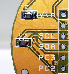
Bypass cap. + autoreset capacitor
| |
|
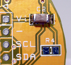
10µF bypass capacitor
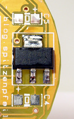
Voltage regulator
| |
|
It'll take about 2-3 seconds until the solder will flow on this one. Lots of thermal mass.
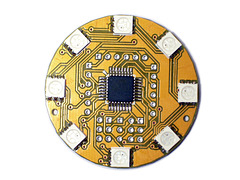
Finished front side - The Spider is waiting
| |
|
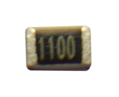
110Ω

Tacking down the RGB LED
| |
|
The white plastic case melts very easily, almost instantly. The PCB on the other hand can withstand a lot of abuse using a 350°C (662°F) iron. Therefore it's OK to place the iron's tip directly onto the board and slide towards the pads. Always try to touch the pads on the PCB first.
Flux it up!
Use Sn60Pb40 solder and 240°C and they will survive.
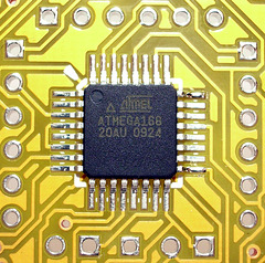
Tacking down the ATmega168
| |
|
Flux the board, align the chip as good as you can and then tack it down. In this case it actually works to apply solder to the tip of the iron and then carry it over to the fluxed pads.
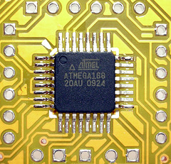
Left side done
| |
|
Nice and shiny. As you can see, I don't use RoHS compliant solder. Tried it and instantly hated it. I didn't want to spend a lot of money for a new soldering station, besides I couldn't get the one I wanted (Hakko).
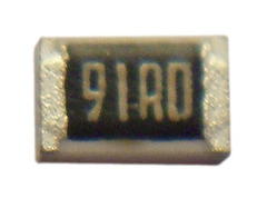
91Ω
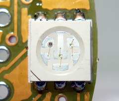
Finished RGB LED
| |
|
The white plastic case melts very easily, almost instantly. The PCB on the other hand can withstand a lot of abuse using a 350°C (662°F) iron. Therefore it's OK to place the iron's tip directly onto the board and slide towards the pads. Always try to touch the pads on the PCB first.
Flux it up!
The LEDs really don't tolerate a lot of rework. Therefore make sure to get it right on the first try.
Use Sn60Pb40 solder and 240°C and they will survive.
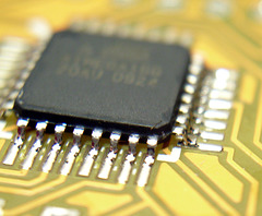
Close up of the pins
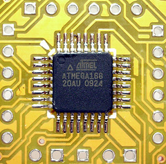
All sides done
| |
|
If you get bridges: clean the tip, add flux to the board and drag the tip away from the part's body.
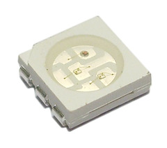
RGB LED
| |
|
The plastic melts very easily. Keep the soldering time to an absolute minimum. Sn60Pb40 solder and 240°C works fine.
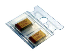
Tantalum capacitors - 10µF
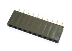
Female header
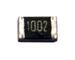
10kΩ
| |
|
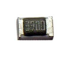
390Ω
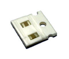
Ceramic capacitors - 100nF
| |
|
