
.:madworm:.'s photos
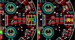
V2.0.d - LED orientation
| |
|
Either populate PLCC6-5050 RGB LEDs or single-color PLCC2 ones. The other 8pcs of small 0805 LEDs are completely optional. They can only be controlled as a whole set using a hardware-PWM pin on Timer0.

BAD BAD 127 / 128 transition
| |
|
The moving average spikes... this is visible as a bright flash ;-(
Very bad when fading - and that is the whole purpose of this exercise.
www.picbasic.co.uk/forum/showthread.php?t=7393
www.picbasic.co.uk/forum/showthread.php?t=10564
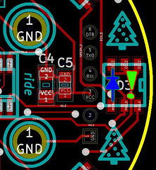
V2.0alpha - LED orientation
| |
|
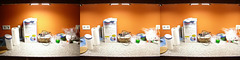
Illumination 1 vs. 2 vs. 3 modules
| |
|
1 to 3 modules with 32pcs 129 lm/W nichia leds each. LED driver: MBI5168, brain: ATtiny2313.
There seems to be a decline in brightness in the middle of the workspace when turning on more modules. I don't know if that is an effect of the camera's exposure program or if I should have used thicker wires for the supply.
V2.0beta - LED orientation
| |
|
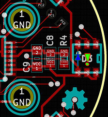
Depending on what type of RGB LED you have, make sure to orient it properly. Use a DMM / diode tester in case of doubt.

Mons capacitivus
| |
|
Formation history is still somewhat unclear, but there are strong hints that a giant pair of tweezers might be involved.

A pyramid
| |
|
Just recently an ancient and seclusive civilization of strange individuals was discovered. The fiercely service and believe in a god called OHM. Nevertheless they are quite often heard talking about de-coupling. It is only assumed that it can't be related to their relationship with their god.
Their secret sign is the Greek Ω

A heap
Iteadstudio 'Mystery PCB' service
| |
|
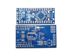
This is what I got . I wonder who will get my boards ;-)
The top one is an 'Arduino Nano V3.0'. I do have suitable ATmega168 chips, headers, probably LEDs and capacitors, but neither do I have an SMD USB receptacle nore the FTDI chip.
The bottom board is a breakout for the FTDI FT232. Assembled versions can be found in their webshop.
There's also a thread on the dangerousprototypes forum about this service.
V2.0 beta - assembly step #7
| |
|
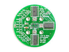
Solder the LED drivers. Make sure orientation is correct to prevent terminal damage.
Beautiful colors
| |
|
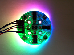
The AVR controls the brightness of the LEDs using 'BCM'. This gives a 6-bit resolution per color channel.
This printed circuit board was ordered at Seeedstudio and uses traces as narrow as 6mil.
It also works with a slightly modified version of the Arduino ShiftPWM library. That delivers extra-smooth color fading.
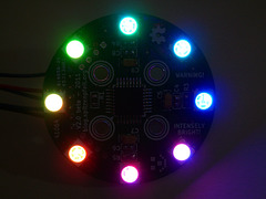
Shot with -2.0EV
| |
|
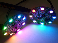
V2.0 beta vs. alpha
| |
|
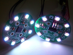
V2.0 beta vs. alpha
| |
|
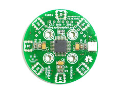
V2.0 beta - assembly step #8
| |
|
Solder the LEDs. Turn down your temperature to about 250°C and use proper SnPb 60/40 solder.
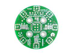
V2.0 beta - assembly step #0.1
| |
|
Inspect the board.
This printed circuit board was ordered at Seeedstudio and uses traces as narrow as 6mil.
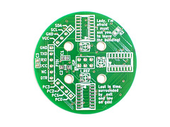
V2.0 beta - assembly step #0.2
| |
|
Inspect the board.
This printed circuit board was ordered at Seeedstudio and uses traces as narrow as 6mil.
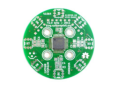
V2.0 beta - assembly step #1
| |
|
Solder down the microcontroller first. Use plenty of flux and check for proper orientation and alignment.
