
.:madworm:.'s photos
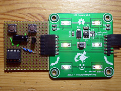
PWM generator added
| |
|
Works nicely - once the soft-start capacitor has been removed and a 10k pull-down resistor has been added.
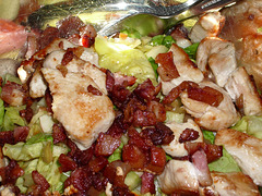
Yummy bacon
| |
|
|
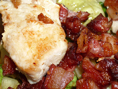
Yummy bacon
| |
|
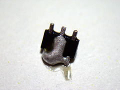
He's dead Jim!
| |
|
The DIM input of the PT4115 is very susceptible to over-voltage - even from a high-impedance source (skin resistance, bridging DIM to VCC).
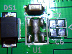
ChipQuik to the rescue

Green on black
| |
|

Triplet
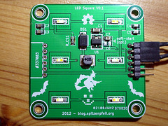
A bit lof light
| |
|
The datasheet says 6V max on the DIM pin... just like on a 5V AVR chip. BUT there don't seem to be any protection diodes in the PT4115. I managed to kill two by accidentally bridging the DIM-pin to the VCC-pin. Not with a wire, but with a finger. Skin resistance was low enough to kill the chip ;-( I've added a 5V1 Zener and a 1k series resistor to the next version.
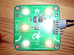
More Light
| |
|
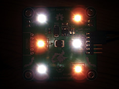
Gloomy
| |
|
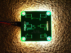
LORK - Light & Cork
| |
|
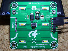
Led Square - done!
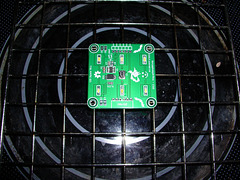
Reflow attempt
| |
|
I have ceran hot plates, which essentially are strong IR heaters, so I just placed the board over it with some distance and played with the dial to simulate the temperature profile for SMD reflow. In the end I just set it to max and turned it off after all parts were done.
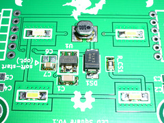
Successful reflow
| |
|
I was terribly afraid of frying the bottom of the board, but it survived unscathed. The ground-plane conducted the heat nicely.
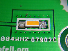
Warm-white LED + paste
| |
|
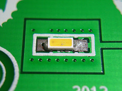
White LED + paste
| |
|
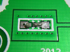
Adding solder paste
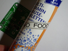
Foolproof marking?
| |
|
I guess I won't mistake it for something edible, but solder paste kind of looks like anchovy paste (which I hate).
