Shuttle Ignition Modification
Folder: Technical, Ham Radio, Photography Etc from 2006
These photos show how I replaced the original 'ignitor' module, after it failed, with a Champion CM418 module. The module selection came from a highly skilled automotive engineer.
17 Nov 2007
Shuttle ignition 025
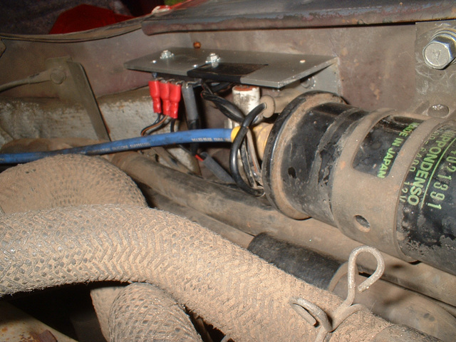
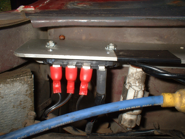
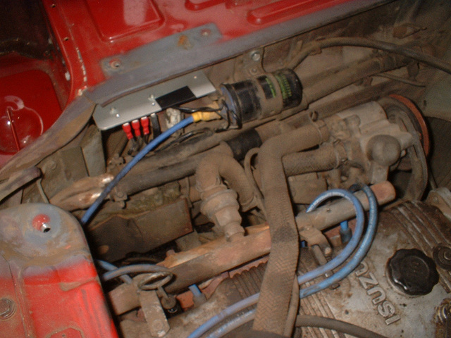
The module, mounted on the heatsink, is screwed to the side of the engine bay just to the rear of the coil. The original wires from the coil to the dizzy are shortened and attached to the module. The connections left to right are Coil-, Coil+, Sensor red, Sensor white. Colour-coded twin is run to the dizzy cable, in sleeving, The original dizzy cable, with connector cut off, is used to enter the dizzy. Correct polarity from the dizzy was determined by experimentation. The engine ran well one way and very poorly the other way.
17 Nov 2007
Shuttle ignition 024
The module, mounted on the heatsink, is screwed to the side of the engine bay just to the rear of the coil. The original wires from the coil to the dizzy are shortened and attached to the module. The connections left to right are Coil-, Coil+, Sensor red, Sensor white. Colour-coded twin is run to the dizzy cable, in sleeving, The original dizzy cable, with connector cut off, is used to enter the dizzy. Correct polarity from the dizzy was determined by experimentation. The engine ran well one way and very poorly the other way.
17 Nov 2007
Shuttle ignition 023
The module, mounted on the heatsink, is screwed to the side of the engine bay just to the rear of the coil. The original wires from the coil to the dizzy are shortened and attached to the module. The connections left to right are Coil-, Coil+, Sensor red, Sensor white. Colour-coded twin is run to the dizzy cable, in sleeving, The original dizzy cable, with connector cut off, is used to enter the dizzy. Correct polarity from the dizzy was determined by experimentation. The engine ran well one way and very poorly the other way.
17 Nov 2007
Shuttle ignition 022
The module, mounted on the heatsink, is screwed to the side of the engine bay just to the rear of the coil. The original wires from the coil to the dizzy are shortened and attached to the module. The connections left to right are Coil-, Coil+, Sensor red, Sensor white. Colour-coded twin is run to the dizzy cable, in sleeving, The original dizzy cable, with connector cut off, is used to enter the dizzy. Correct polarity from the dizzy was determined by experimentation. The engine ran well one way and very poorly the other way.
17 Nov 2007
Shuttle ignition 021
The module, mounted on the heatsink, is screwed to the side of the engine bay just to the rear of the coil. The original wires from the coil to the dizzy are shortened and attached to the module. The connections left to right are Coil-, Coil+, Sensor red, Sensor white. Colour-coded twin is run to the dizzy cable, in sleeving, The original dizzy cable, with connector cut off, is used to enter the dizzy. Correct polarity from the dizzy was determined by experimentation. The engine ran well one way and very poorly the other way.
13 Nov 2007
Shuttle ignition 020
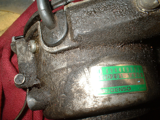
Cable entry to dizzy. the screw to its left is one of the two ignitor mounting screws.
Jump to top
RSS feed- Latest items - Subscribe to the latest items added to this album
- ipernity © 2007-2024
- Help & Contact
|
Club news
|
About ipernity
|
History |
ipernity Club & Prices |
Guide of good conduct
Donate | Group guidelines | Privacy policy | Terms of use | Statutes | In memoria -
Facebook
Twitter


