Failre by Design
Folder: Electronics
Not very intelligently designed contraptions. Some products are just insanely bad, other may just have some aspects of failure.
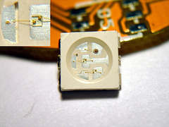
Dead RGB LED
| |
|
Once in a while I sell one or two of the RGB LED RING boards. As not everybody feels comfortable with soldering SMD parts (and I've explicitly warned that it's not that easy and that the RGB LEDs die easily) I do some 'contract soldering' from time to time as well.
Today I've killed 3 - THREE - of these friggin' things, and I only have about 10 spares left. That's a loss of more than 1€ of semiconductor. Time to get more spares it seems.
In this shot I managed to show what's going belly up here. It's always the green ones that die. As shown here, the bonding wire has been ripped off the left pad due to stress.
Looking at this image again a few hours later, it seems the whole pad has moved to the left opening a gap of maybe 0.1mm. What a heap of shit. Could the surface tension of the solder create such a big force and pull the pad out of the somewhat softened plastic body?
I'm trying to keep the heat down and be quick, but today was a very bad soldering day. I have a feeling they wanted to save time and material in the bonding process and the wires are a bit overstressed anyway. Maybe they also 'tweaked' the gold content a bit and it got too brittle.
If these LEDs are soldered in a reflow oven this problem might not occur at all, as the epoxy around the wires will soften a bit. Given the correct temperature-vs-time profile is used. Time to get an SMD toaster? Maybe. Any recommendations? Hotplate? And I don't want to spend a fortune on it as well. Oh BTW, I hate things that suddenly just sublimate without any signs of warning! I'm looking for reasonably priced quality products here. Nothing fancy, but fully functional with a minimal amount of cursing.
Today was also the very first time that I just couldn't reliably upload code using a bootloader with the chip running on the internal 8MHz RC oscillator. Maybe this is due to the somewhat elevated temperatures we're having here right now. It's in the middle of the night right now and I'm still getting 26°C in my room. Or maybe this AVR's factory calibration is just terribly wrong. Luckily I had previously assembled another one of the boards, so I just swapped them. The good one is sent away and I keep the rebellious one for further testing. I'll put it into the freezer tomorrow and see what happens to it.
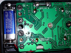
No external fuse access ;-(
| |
|
I've blown this fuse again. One reason might be that I use 160mA ones instead of 500mA. Why? I have one, but not the other.
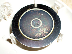
Piezo buzzer - oxidized
| |
|
No wonder the buzzer wasn't working properly any more. They should have soldered wires to it instead of using spring contacts. "Planned obsolescence" at work?
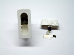
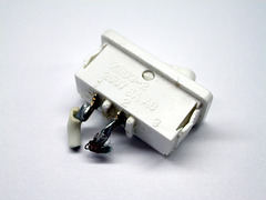
Crappy switch
Crappy switch
| |
|
Quality switches just don't come in this small size. No replacement can be found for this one. The main issue is the depth of it.
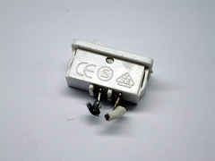
Crappy switch
| |
|
The CE sign is fake!
en.wikipedia.org/wiki/CE_mark
www.flickr.com/photos/linux-works/4443742355/
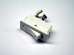
Crappy switch
| |
|
This switch is part of cheap light fixtures under my kitchen cupboards. I got them several years ago. One switch has gone bad and I've been trying to get it replaced for months, if not years. Suffice to say I just couldn't find any replacement that would fit. Now I've just bridged the wires and covered the hole. I'll have to put a switch into the supply line. That way I'll also put less stress on the remaining switches of this terrible kind.
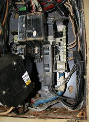
Breaker Box
| |
|
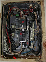
A fine example of the work of 'skilled' Texan electricians.
The AC heat exchanger was right above it and condensed water was dripping into the braker box :-(
Breaker Box
| |
|
Complete chaos.
I don't remember if there was a GFI in there at all.
During the time my AC was down (ONE frigging weak with temperatures in the high 90s) I was sleeping with the apartment door wide open. Thankfully i wasn't robbed, mugged or even offed.
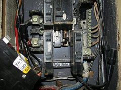
Breaker Box
| |
|
The guy how tried to snap-in the new breaker didn't push hard enough. So the right rail got hot due to bad contact. The old breaker wasn't up to the current the AC was pulling. Btw. the AC broke down as well and they managed to wreck the replacement compressor right away :-)
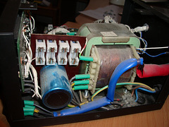
My digital power supply
| |
|
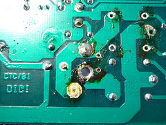
The left two fuses were blown, having a very unfortunate effect.
Also what bugs me a lot is that the screws used to keep everything in place are made of a particularly soft iron. They literally 'melt' away when loosening them with a standard (and matching) screwdriver. I'll have to replace all of them.
Overheated shunt resistor
| |
|
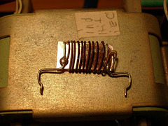
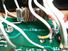
The left one got too hot. It was running a few hours at maximum current (about 2.8A). As I found out later, it ran in unregulated mode, as two fuses were blown. The power to the microcontroller was cut off.
After replacing the two 100mA fuses with 160mA ones it works again. I just happened to have them, but I'll need to get proper ones. The shunt resistor will have to be replaced as well, as its insulation is breaking down. I've measured it to be 0.4Ω, but I can't trust that value. Maybe the manufacturer will tell me the correct resistance.
Overheated shunt resistor
| |
|
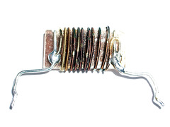
Old shunt resistor
| |
|
I've retired this one, but kept it. Just in case ;-)
It was replaced by a standard 10% 5W 390mΩ resistor. Not perfect, but it works good enough for me. The worst deviation I've measured is less than 5%.
Overheated shunt resistor
| |
|
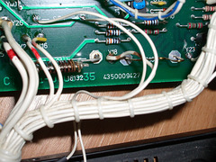
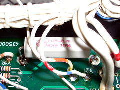
Digi 35 CPU - new shunt resistor
| |
|
I couldn't get hold of a precision shunt resistor, so I had to do with this 10% 5W one here. It didn't turn out too bad at all. This one doesn't affect the current displayed on the power supply's display (the display measures the current itself), but the current set-point in the opamp feedback loop. I have a schematic, but it is not quite matching the PCB revision I have, so I couldn't instantly figure out which pot to tweak to compensate for small deviations. Reverse engineering a schematic from a given PCB sucks.
I compared the current set on the power supply (via a keypad) and the current measured by a good multimeter and it wasn't off by more than 5% worst case. That's good enough for me right now.
Removing a relay
| |
|
At first I thought one relay was broken, but it turned out to be a classical "failure by design". More on that on my blog.
Digital power supply
| |
|
BMOW.
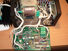
The bottom right chips are two DACs. Either they're used to drive the power transistors, or (which would be a sad thing) they're used to drive the LC displays on the front.
The two green relays are used for two thing: a) connect/disconnect the voltage from the screw terminals on the front, b) short + to - for offline current adjustment. This plays an important role when the fuses for the microcontroller blow.
Both relays are SPDT. One is connected as "normally closed", the other one as "normally open".
Jump to top
RSS feed- Latest items - Subscribe to the latest items added to this album
- ipernity © 2007-2024
- Help & Contact
|
Club news
|
About ipernity
|
History |
ipernity Club & Prices |
Guide of good conduct
Donate | Group guidelines | Privacy policy | Terms of use | Statutes | In memoria -
Facebook
Twitter

